Fuses and relays in 2007-2011 model year 2.4 Tdci Puma Defenders are mounted in one of two fuse boxes. One fuse box is located under the RH front seat, and the other is located below the steering wheel.

The battery is mounted in a protective box, located under the LH seat. It sits in a tray and is secured with clamp plates and bolts. The battery terminal posts allow for the battery cables to be connected with clamp type connections.
The battery positive terminal is fitted with a mega fuse, which is a 500 Amp device housed in a black fuse carrier, integral to the battery clamp and is integral with the cable assembly. In the event of fuse failure, the complete cable assembly must be replaced. The power feed to the BJB is taken from a tap on the battery clamp before the mega fuse. In the event of a crash the mega fuse is designed to blow, this isolates the power from the generator and starter motor, but allows power to be delivered, via the central junction box (CJB), to the rest of the vehicle.
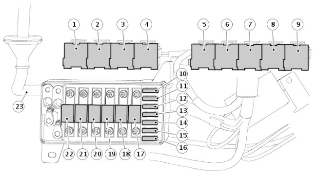
The under seat fuse box is also known as the "Battery Junction Box" and is where most of the relays are located. Power comes to this unit via a cable directly from the battery. This fuse box feeds all other circuits in the vehicle.
| ID | Function |
|---|---|
| 1 | ABS pump relay |
| 2 | Main relay |
| 3 | Starter relay |
| 4 | Glow plug relay |
| 5 | A/C clutch relay |
| 6 | A/C cooling fan relay |
| 7 | A/C accessory relay |
| 8 | Heated front screen relay |
| 9 | Heated screen timer relay |
| ID | Rating | Colour | Circuits supplied |
|---|---|---|---|
| 17 | 30A | Green | Lighting switch |
| 18 | 60A | Yellow | Ignition switch, starter motor relay |
| 19 | 30A | Green | ABS return pump relay |
| 20 | 60A | Yellow | Electric window relay |
| 21 | 60A | Yellow | Feed to under dash fuse box |
| 22 | 100A | Blue | Glowplug relay, fusible links 2, 3, and 4, fuses 1, 2, and 3 of the under seat fuse box, fuse 36 of the under dash fuse box |
| ID | Rating | Colour | Circuits supplied |
|---|---|---|---|
| 10 | 20A | Yellow | Alarm system |
| 11 | 15A | Blue | Alarm system |
| 12 | 30A | Green | Main relay, engine control module (ECM) |
| 13 | 20A | Yellow | Not used |
| 14 | 20A | Yellow | Headlamp flash/horn |
| 15 | 20A | Yellow | Accessory socket |
| 16 | 30A | Green | ABS system |
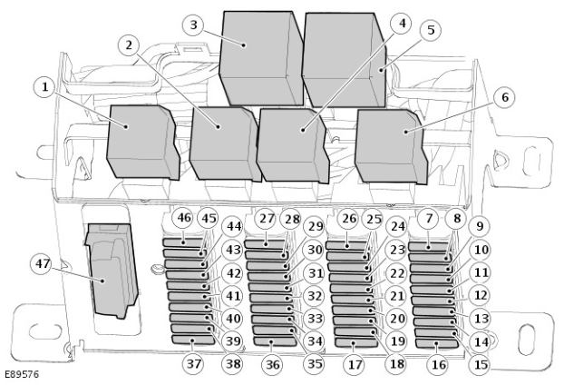
The under dash fuse box is also known as the "Central Junction Box". It is located below and to one side of the steering column. The fuses are accessed by turning the fixing screws fully counterclockwise and removing the cover.
Some early 07MY vehicles have a handed CJB. The illustration below shows the left-hand (LH) drive variant fitted to all other vehicles. The early right-hand (RH) drive version is a mirror image of the standard LH drive CJB.
| ID | Function |
|---|---|
| 1 | Headlamp relay |
| 2 | Heated rear window relay |
| 3 | Wiper relay |
| 4 | Electric window relay |
| 5 | Indicator flasher relay |
| 6 | Alarm relay |
| ID | Label | Rating | Colour | Circuits supplied |
|---|---|---|---|---|
| 7 | F17 | Not used | ||
| 8 | F16 | Not used | ||
| 9 | F15 | 5 | Tan | Ignition |
| 10 | F14 | 10 | Red | Reverse lamp |
| 11 | F13 | 10 | Red | Brake lamps |
| 12 | F12 | 10 | Red | Speed transducer |
| 13 | F11 | 10 | Red | ABS system |
| 14 | F10 | 10 | Red | Rear wipers/wash |
| 15 | F9 | 15 | Blue | Front wipers/wash |
| 16 | F8 | 10 | Red | Alarm system |
| 17 | F18 | 10 | Red | Side lamps (left) |
| 18 | F19 | 10 | Red | Side lamps (right) |
| 19 | F20 | 10 | Red | Instrument illumination |
| 20 | F21 | 10 | Red | Hazard switch |
| 21 | F22 | 10 | Red | Headlamp dipped beam (right) |
| 22 | F23 | 10 | Red | Headlamp dipped beam (left) |
| ID | Label | Rating | Colour | Circuits supplied |
|---|---|---|---|---|
| 23 | F24 | 10 | Red | Headlamp main beam (right) |
| 24 | F25 | 10 | Red | Headlamp main beam (left) |
| 25 | F26 | 10 | Red | Rear fog lamps |
| 26 | F27 | 10 | Red | Alarm sounder |
| 27 | F37 | 30 | Green | Spare fuse |
| 28 | F36 | 30 | Green | Heated front screen |
| 29 | F35 | 20 | Yellow | Electric window (left) |
| 30 | F34 | 20 | Yellow | Electric window (right) |
| 31 | F33 | 20 | Yellow | Seat heaters |
| 32 | F32 | Not used | ||
| 33 | F31 | 15 | Blue | Hazard switch |
| 34 | F30 | 10 | Red | Audio/clock/diagnostic socket |
| ID | Label | Rating | Colour | Circuits supplied |
|---|---|---|---|---|
| 35 | F29 | 20 | Yellow | A/C clutch/cooling fan |
| 36 | F28 | 20 | Yellow | Heated rear window |
| 37 | F38 | 10 | Red | Engine ECU/PCM |
| 38 | F39 | 5 | Tan | Engine ECU/PCM |
| 39 | F40 | Not used | ||
| 40 | F41 | 5 | Tan | Engine ECU/PCM |
| 41 | F42 | 10 | Red | A/C switch |
| 42 | F43 | 20 | Yellow | Accessory socket/cigar lighter |
| 43 | F44 | 5 | Tan | Audio unit |
| 44 | F45 | 30 | Green | Blower motor |
| 45 | F46 | Not used | ||
| 46 | F47 | Not used | ||
| 47 | Diagnostic socket | Diagnostic socket |